Commercial Sewage Treatment Plants
SAF (submerged aerated filter) technology for maximum performance and reliability
The Bio-Pure Flowpath for Commercial, Industrial or larger off mains applications
The Bio-Pure Flowpath for Commercial, Industrial or larger off mains applications
We Build It Ltd have developed its range of package Sewage Treatment Plants utilising proven SAF (submerged aerated filter) technology for maximum performance and reliability, using the most reliable energy efficient aeration blowers with a prolonged integral flow path system to maximise effluent retention time and quality.
Our standard plant range offers treatment to a 30mg/l BOD: 20mg/l SS effluent quality standard with options for 30mg/l NH3 effluent quality.
All our treatment plants are designed in accordance with the British Water Code of Practice for flows and loads, the Bio-Pure FlowPath range can be designed to meet your population requirements.
The plants can be single or modular tanks depending on population and consent requirements.
BIO-PURE FLOWPATH COMMERCIAL SEWAGE TREATMENT PLANTS
Features and Benefits
A List of typical application of 10mg/l BOD;10mg/l S.S; 5mg/l NH3 can be achieved
Friendly telephone support
Effluent standard: 20mg/l BOD; 30mg/l SS; 20mg/l NH3
Below Ground Installation (Can be adapted for above ground applications)
Higher rate nitrification also available
Easy to install, suitable for installation with either granular or concrete backfill
Energy efficient air blower for lower running costS
SAF technology with reliable performance
High efficiency, tailored solutions
Typical De-Sludge period is approximately 12 months depending on demand
2 year manufacturers warranty on all air compressors
Option for pumped units (inlet and outlet effluent)
25 year warranty on all GRP components
No moving parts
Servicing contracts by our team of trained technicians
Quiet and odourless operation
Deeper installations can be accommodated
Any Invert levels can be accommodated
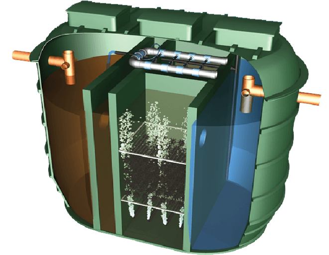
HOW THE FLOW PATH WORKS
The Bio-Pure Flow Path commercial sewage treatment plant contains, a two stage primary settlement zone designed to settle coarse and non-biological loadings.
Sludge will build up in these zones and require moving periodically.
The Settled effluent will then discharge forward into the bio-zones. Each segment field contains a high percentage of filter media, where biological treatment performs , due to a high oxygen input.
Once treatment has taken place the multiple bio-zones, the effluent is discharged into the final humus tank, where it settles before flowing via the outlet.
Occasionally an amount of settled humus sludge is returned to the first primary zone.
FLOW PATH MAINTENAINCE
The benefits in our service agreements which are listed below
Emergency breakdown cover for 12 months. If you have any problem with your unit, call us and we will come out and fix it free of charge.
Two service visit per year where all necessary checks are carried out. This includes checking the blower filters, check control panel and connections are sound, Air vents and louvers into the kiosk are free from debris, assessing the aeration pattern, sludge levels and effluent quality.
All labour expenses for servicing and call outs are covered so there are no hidden costs.
The cost of all serviceable parts will be free of charge. This includes, replacing the control panel air filters and carbon filters replacements.
Replacement parts are at a discounted.
Ensuring floating sludge is no thicker than 150mm and the settled sludge is at least 1 meter below the top water level.
Emptying is NOT included in the agreement.
Bio-Pure Flow Path Installation
Note : These guidance notes refer only to the installation of Concrete surround underground tanks. These guidance notes cannot provide specific, site-related installation instructions. If in any doubt whatsoever about any aspect of the installation, please contact We Build It Ltd 01746781782
Service Specification
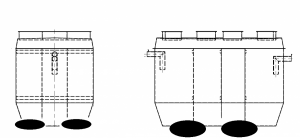
These tanks are designed to be installed below ground and completely surrounded with concrete.
Generally, the depth from finished ground level to the top crown of the main shell should be no more than 2 metres. This may vary dependant upon ground water conditions.
Deeper inverts may be accommodated on a standard shell providing the water table level does not exceed 2 metres above the top crown of the main shell. For deeper burial with high water table conditions heavy duty shells are available.
Should you be in any doubt regarding suitable shell application please call our Technical Sales Office on 01746781782
If the tank is installed outside these parameters it may suffer irreparable damage.
Concrete Specification
The specification for the concrete mix to surround the tank may be taken from BS 5328 : Part 1 : 1991 (including amendments), taking into account the site conditions and application requirements. For a typical non-structural application in non aggressive soils a Standard Mix ST4 with a 50mm slump is generally suitable, but also permits the equivalent Designated Mix GEN3 to be specified as an alternative. If for non typical applications, structural or other reasons a higher than normal designation is required, the purchaser of the fresh concrete can use table 6 in BS 5328: Part 2: 1991 (amendment 8759/October 1995) for guidance.
Lift height (rate of rise)
Determine the lift height (m), or rate of rise (m/h) for the specific concrete type used, to ensure that a design pressure (P max) of 15kN/m2 on the tank is not exceeded.
Vibration
The design of the tank assumes minimal compaction of the surrounding concrete. Where necessary, this may be extended to include light internal vibration. Never use deep revibration which will substantially increase the pressure on the tank, possibly causing failure.
Impact of Concrete on Discharge
The effects of impact on discharge are considerable. These are controlled by the vertical form height, the tank diameter and the method of discharge. Under no circumstances should concrete be discharged directly onto the tank.
Loadings
If the tank is installed in an area where traffic or other superimposed loadings can be applied, consult a structural engineer for the design of a reinforced concrete slab to prevent the load being transmitted to the tank (or its concrete surround). If this slab is constructed immediately above the tank, it should be separated from the concrete surrounding the tank by a compressible material.
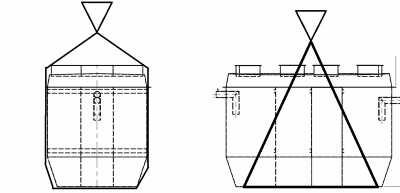
Transportation, unloading and storage of tanks
- Tanks must be held down during transportation using nylon straps, do not use cables or chains to hold tanks
- Do not over tighten straps to cause deformation of the tank shell
- Tanks are best lifted by crane and webbing lifting straps – do not use chains or wire ropes in contact with the tank.
- We Build It Ltd recommends the use of a lifting beam for tanks longer than 8 metres
- Smaller tanks may be lifted with other suitable site equipment but greater care is needed to control the lift and to ensure the tank is not damaged.
Pre-Installation Inspection
- Tanks should be subject to a visual inspection prior to installation
- Special consideration should be given to lifting strap positions
- Any damage should be notified to the delivery driver and to We Build It Ltd
- Do not attempt to carry out any unauthorised repairs, as this will invalidate the
Warranty on the tank - Check for, fractures to the shell or ribs, de laminations, scratches or abrasions deeper than 1.5mm, stress cracks or star crazing
- Check invert depth is correct and inlet and outlet pipe orientations are correct
Installation procedures must be in accordance with the Health and Safety at Work Act 1974, and other relevant legislation. Your procedures must also align with good building practice.
NOTE: Check that the depth to the base slab is within the Service Specification requirements for the tank.
- Excavate for the tank, allowing sufficient clearance for the minimum concrete surround thickness as shown in the table below, whilst also considering any shoring / trench supports used. The depth of the excavation is determined by the inlet and outlet pipe invert levels relative to the bottom of the tank, and allowing for the minimum base thickness shown. Dimensioned details of the separator can be taken from the relevant drawing. Ground instability at formation level e.g. running sand may necessitate over-excavation and stabilisation with hardcore or blinding concrete.
- Maintain a completely dry excavation until the final pour of concrete has set. Failure to do this may result in voids beneath the tank and subsequent tank failure.
- Pour the concrete into the bottom of the excavation to form a level and smooth base onto Which the tank can sit. This should be to the minimum thickness given in the table above.
- Place the tank onto the concrete base, while the concrete is still wet, and determine the Correct orientation for the tank inlet(s) and outlet(s), i.e. the higher pipe on the tank is To be connected to your upstream (inlet) pipe work and the lower pipe on the tank is to be connected to your downstream (outlet) pipe work. Connect and seal your pipe work to the tank, checking alignment, and ensure that there is an adequate and correct fall for each pipe.
- Fill each chamber of the tank with clean water to a depth of 300mm and recheck the pipe work levels. Commence backfilling evenly around the tank with concrete ensuring there are no voids, particularly at the bottom of the tank shell. Continue filling the chambers with water whilst evenly backfilling with concrete ensuring that the progressive water level is no more than 300mm above the concrete level.
- Connect and seal turret extensions prior to completing the concrete encasement of the main tank to the height shown in the table. Allow this concrete to set.
- Using appropriate formwork, continue pouring concrete around the tank superstructure (i.e. bypass chamber, access turrets) in lift heights not exceeding 500mm, allowing initial set between each lift.
- Complete backfill to ground level using free flowing material. Trim all access turrets and prepare suitable footings for each manhole frame ensuring that any loads on the covers are not transmitted to the tank access turrets or access extensions, if fitted.
NOTE: Never increase the lift height or accelerate the rate of rise for the concrete type used, or allow the concrete to be compacted to an extent which will cause any part of the tank superstructure to distort. If you contravene this warning you will cause damage to the tank.
Control of Groundwater
Tanks must not be subjected to buoyant forces during installation, taking account of ground water levels and surface water run-off, and their accumulation in the tank pit, even if tanks are anchored. The excavation should be maintained dry by pumping or whatever suitable means until the concrete surround is cured
Access Shaft Extensions
Access extensions shall be surrounded with concrete poured in 500mm lifts allowing initial set between each lift. The pressure from concrete placed in higher lifts may cause access extensions to distort or collapse.
Please note that loose shafts should be sealed using silicon sealant sikaflex –291 or similar prior to installation to prevent ingress of groundwater under high water table conditions. It is the contractor’s responsibility to ensure a watertight seal.